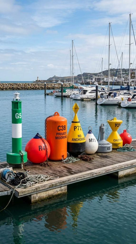

Global buoyage regulations are governed by the IALA Maritime Buoyage System (MBS) (Edition 8.1, 2023). Under this strictly enforced international framework, the six primary marks are Port-Hand, Starboard-Hand, Preferred Channel (Port Bifurcation), Preferred Channel (Starboard Bifurcation), Fairway (Safe Water), and Isolated Danger.
To ensure safe and efficient maritime operations, port authorities, marine engineers, and offshore operators must rigorously understand the six main types of buoys. These standardized markers are critical physical fail-safes for delineating navigable channels and isolating submerged hazards in complex waterways.
Key Takeaways
- Standardized Authority: Global buoyage architecture must comply with the IALA Maritime Buoyage System (MBS Section 2.1).
- Regional Variations: The globe is split into IALA Region A and Region B. While topmark silhouettes (shapes) remain uniform globally, chromaticity (color) conventions for lateral marks invert depending on the region (IALA MBS Section 2.4).
- Direction of Buoyage: Navigational compliance relies on the “conventional direction of buoyage,” legally defined as the route a vessel takes approaching a harbor, estuary, or river from the open sea (UKHO NP735, Section 1.3).
- AtoN Payload Scalability: Modern maritime infrastructure dictates that navigation marks function as high-buoyancy platforms for meteorological telemetry and heavy-duty water quality monitoring arrays, requiring precise reserve buoyancy calculations.
The IALA System: Region A and Region B Navigation Buoys
Before engineering mooring systems or deploying physical markers, waterway managers must recognize that the IALA divides global maritime jurisdictions into two distinct systems. The primary structural difference is the chromatic convention applied to lateral marks.
- IALA Region A (Europe, Australia, Asia including Hong Kong & Mainland China, Africa):
- Navigational Rule: Port marks are Red; Starboard marks are Green (IALA MBS Section 3.2).
- IALA Region B (Americas, Japan, South Korea, Philippines):
- Navigational Rule: Port marks are Green; Starboard marks are Red (standardized in North America via the USCG mnemonic “Red Right Returning”).
Empirical Safety Principle: In deteriorating visibility—such as heavy coastal fog or sea spray—chromatic signatures wash out before silhouettes do. The physical geometry of the mark (Can for Port, Cone for Starboard) is a universally reliable radar and visual identifier, explicitly mandated in the USCG Light List, Volume 1 (COMDTINST M16502.2J).
The Six Essential Types of Maritime Navigation Buoys

1. Port-Hand Buoys
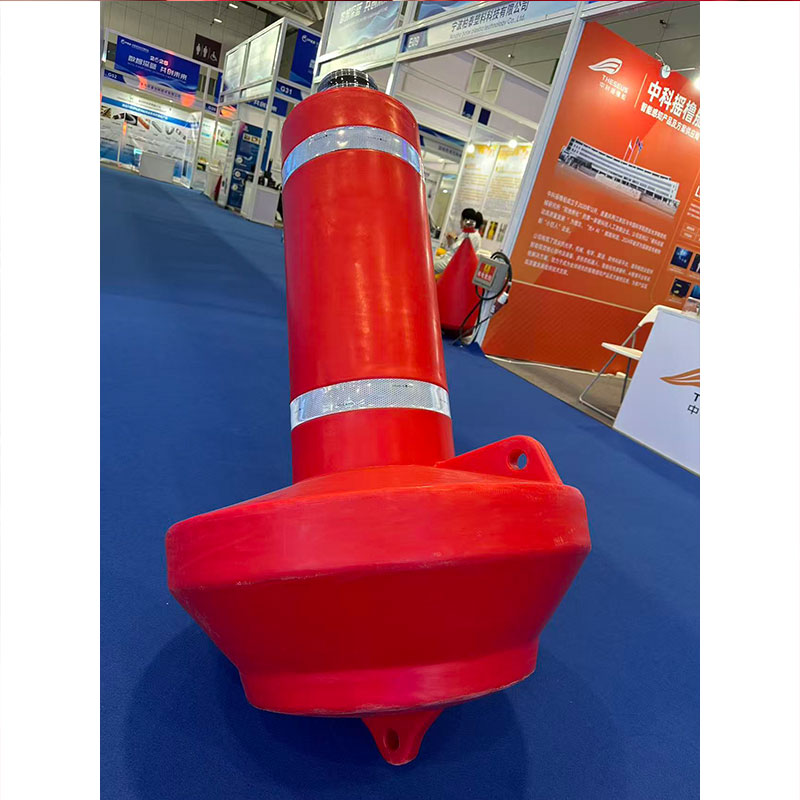
Port-hand buoys dictate the left-hand limit of a navigable channel when a vessel proceeds in the conventional direction of buoyage.
- Shape: Strictly Can (cylindrical) or a pillar/spar with a can-shaped topmark (IALA MBS Section 3.1).
- Color (Region A): Red.
- Color (Region B): Green.
- Light Characteristics: Matches the buoy’s focal color with any rhythm except composite group flashing.
- Numbering: In Region B jurisdictions, port marks utilize odd numbers that increase sequentially from seaward (USCG AtoN System, Section 4.A).
2. Starboard-Hand Buoys
Starboard-hand buoys dictate the right-hand limit of a channel when heading inland.
- Shape: Strictly Conical (cone) or a pillar/spar with a cone-shaped topmark pointing upward.
- Color (Region A): Green.
- Color (Region B): Red.
- Light Characteristics: Matches the focal color (e.g., Q.G or Fl.G in Region A).
- Numbering: Where applied, starboard marks carry even numbers increasing from seaward.
3. Port Bifurcation (Preferred Channel) Buoys
Moored precisely at channel junctions, these buoys signal the primary (deepest/widest) route. A Port Bifurcation buoy signals that the preferred channel is to the left.
- Shape: Cylindrical (Can).
- Color (Region A): Red with a green horizontal band.
- Color (Region B): Green with a red horizontal band.
- Light: Composite group flashing (2+1) matching the uppermost color band (IALA MBS Section 3.5).
4. Starboard Bifurcation (Preferred Channel) Buoys
A Starboard Bifurcation buoy indicates that at a channel split, the preferred, safer route is to the right.
- Shape: Conical (Cone).
- Color (Region A): Green with a red horizontal band.
- Color (Region B): Red with a green horizontal band.
- Light: Composite group flashing (2+1) matching the uppermost color band.
5. Fairway (Safe Water) Buoys
Fairway buoys denote that navigable water surrounds the infrastructure on 360 degrees. They serve as centerline marks or initial seaward landfall marks (IALA MBS Section 5.1).
- Color: Red and white vertical stripes.
- Shape: Spherical, pillar, or spar.
- Topmark: A single red sphere.
- Light: White light showing an Isophase (Iso), Occulting (Oc), one Long Flash every 10s (LFl.10s), or Morse code “A” (Mo(A)) pattern.
6. Isolated Danger Buoys
Deployed directly over highly localized hazards (e.g., submerged wrecks, rock pinnacles) that are completely surrounded by navigable water (IALA MBS Section 4.1).
- Color: Black with one or more broad red horizontal bands.
- Shape: Pillar or spar.
- Topmark: Two black spheres aligned vertically.
- Light: White light, flashing in groups of two (Fl(2)).
Quick Reference Tables for Identifying Navigation Buoys

Source data strictly derived from the IALA Maritime Buoyage System, 8th Edition (2023).
Lateral Marks by IALA Region (Action based on heading inland from sea)
| Buoy Type | Topmark Silhouette | Region A (Europe/Asia) | Region B (Americas/Japan) | Navigational Action |
| Port-Hand | Can (Cylinder) | Red | Green | Keep on port (left) side. |
| Starboard-Hand | Cone (Point Up) | Green | Red | Keep on starboard (right) side. |
| Pref. Ch. (Left) | Can (Cylinder) | Red w/ Green Band | Green w/ Red Band | Pass left for primary channel. |
| Pref. Ch. (Right) | Cone (Point Up) | Green w/ Red Band | Red w/ Green Band | Pass right for primary channel. |
Universal Marks (Consistent globally in both Region A and B)
| Buoy Type | Chromatic Pattern | Topmark Silhouette | Light Phase |
| Fairway (Safe) | Red & White Vertical Stripes | Single Red Sphere | White (Iso, Oc, LFl, Mo(A)) |
| Isolated Danger | Black w/ Red Horizontal Bands | Two Black Spheres | White Flashing (Fl(2)) |
Empirical Case Study: Deploying Mooring Systems for Marine Buoys
Translating IALA theoretical standards into physical infrastructure requires rigorous marine engineering. Standard taut-line depth multipliers (e.g., blindly using a 3:1 scope) frequently fail in high-current tidal zones, leading to the anchor dragging and the AtoN drifting off-station.
Catenary Mooring Dynamics in the Pearl River Estuary:
During a recent infrastructure upgrade in a highly trafficked Region A estuary, marine engineers were tasked with deploying 2.5-meter diameter monitoring buoys in a channel with a maximum depth (D) of 15 meters, subjected to 4-knot tidal currents and 50-knot gale wind loads. To prevent the anchor from dragging, the mooring chain must absorb the kinetic energy of the environment by forming a catenary curve on the seabed.
According to IALA Guideline G1066 (Design of Floating AtoN Moorings, Section 4.2), engineers must calculate the absolute minimum chain length (L_min) required to maintain zero vertical uplift on the sinker:
L_min = Square Root of (D^2 + (2 * D * T_H) / w)
Where:
- D = Maximum water depth at Highest Astronomical Tide (HAT).
- T_H = Total horizontal environmental tension (combined current drag + aerodynamic wind load on the buoy profile).
- w = Submerged weight of the mooring chain per linear meter.
In this field deployment, engineers utilized Grade 3, 38mm stud-link chain (w approximately 28 kg/m submerged). Calculating the exact T_H based on the buoy’s drag coefficient dictated a chain length significantly longer than a standard 3:1 rule of thumb. Failing to execute this exact catenary calculus results in a compromised “watch circle,” mathematically guaranteeing the buoy will drift into the shipping lane during storm surges, creating a severe, liable navigational hazard.
Infrastructure Procurement: Why Engineers Specify Botai Heavy-Duty Buoys
Commercial Annex: The following section outlines proprietary B2B material specifications and operational capabilities for marine infrastructure procurement teams.
Equipping commercial shipping lanes, offshore dredging operations, and environmental monitoring zones requires infrastructure engineered to survive extreme kinetic impacts while strictly maintaining IALA photometric standards. With exactly 15 years of heavy-industrial manufacturing pedigree, Botai engineers marine components tailored exclusively for these high-stress offshore environments.
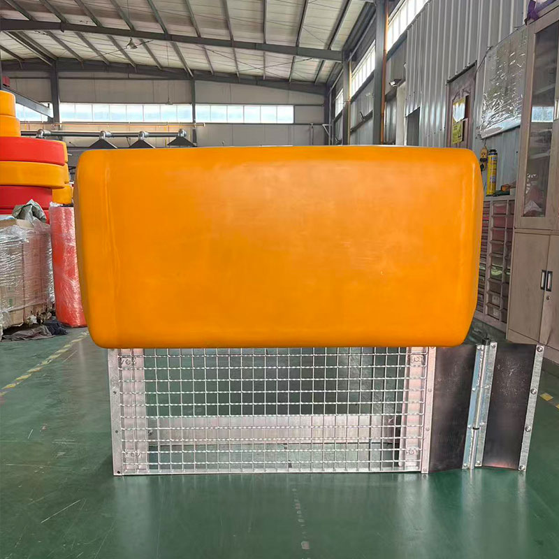
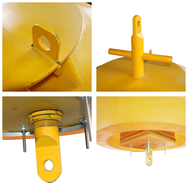
Botai’s manufacturing capabilities are strictly dedicated to heavy-duty commercial applications—specializing in massive navigation markers, dredging pipe floaters, and customized water quality monitoring buoys. To guarantee uncompromising structural integrity across our facilities, we intentionally exclude low-tier, light-duty consumer plastics (such as hose floats) from our production scope.
Technical Specifications for Botai Marine Engineering Components:
- Kinetic Impact Resistance: Fabricated via advanced heavy-industrial rotomolding from virgin, high-impact polyethylene (PE). The thick-walled, seamless hull is engineered to flex and absorb the kinetic energy of vessel strikes, vastly outperforming aging steel (which dents and rusts) or rigid fiberglass (which shatters).
- Unsinkable Architecture: The internal cavity is injected with high-density, closed-cell polyurethane foam. Even following a catastrophic hull breach from a propeller strike, the closed-cell matrix physically blocks water ingress, ensuring the AtoN remains afloat, visible, and fully operational.
- UV-Stabilized Chromaticity: Premium UV-resistant pigments are compounded directly into the PE matrix before the rotomolding process. This guarantees that the precise IALA red, green, black, or yellow chromaticity limits remain compliant under intense marine solar radiation, eliminating the prohibitive lifecycle OPEX of sandblasting, priming, and repainting steel marks.
FAQ
Where are the official regulatory documents governing international buoys found?
The definitive global authority is the Maritime Buoyage System and Other Aids to Navigation published by the IALA. For localized deployment specifics and exact light rhythms, marine engineers must consult national hydrographic documents, such as the USCG Light Lists (United States) or the UKHO’s NP735 (United Kingdom).
Why is relying on a buoy’s physical shape critical during night navigation?
Ambient light pollution from coastal infrastructure (urban backscatter) often washes out a buoy’s colored LED signature. Relying on the distinct flashing rhythm (e.g., Composite Group Flashing 2+1 for Bifurcation) and verifying the silhouette (Can vs. Cone) via marine radar ensures unambiguous identification, negating both backscatter interference and color vision deficiencies among bridge crew.
What is the OPEX difference between rotomolded polyethylene and steel buoys?
Rotomolded polyethylene drastically reduces long-term operational expenditure (OPEX). PE is biologically inert, preventing severe marine bio-fouling, and is completely immune to galvanic corrosion. Maintenance cycles are heavily reduced to simply lifting the asset to inspect sub-surface mooring shackles for abrasion and wiping down the integrated solar lantern panels.
Authoritative References and Resources for Navigation Buoys
To ensure waterway infrastructure planning is safe, mathematically rigorous, and legally compliant, procurement and marine engineering teams should consult the following primary texts:
- IALA-AISM (2023): Maritime Buoyage System and Other Aids to Navigation, Edition 8.1. The definitive global standard for visual Aids to Navigation (AtoN) parameters (Sections 1-5).
- IALA Guideline G1066: Design of Floating Aid to Navigation Moorings. Authoritative engineering guidelines for calculating safe watch circles, catenary chain dynamics, and anchor loads.
- United Kingdom Hydrographic Office (UKHO): NP735 – IALA Maritime Buoyage System, 8th Edition. Essential reference manual for applying the MBS within navigational workflows.
- United States Coast Guard (USCG): U.S. Aids to Navigation System (COMDTINST M16502.2J). Official regulatory documentation detailing Region B implementation, specific numbering protocols, and regulated light rhythms.
- USCG Light List Annual Publication: Light List (Volume 1-7). The primary database for technical specifications and operational status of all U.S. federal aids to navigation.
Safety & Regulatory Disclaimer: The navigational specifications detailed in this technical briefing synthesize the official International Association of Marine Aids to Navigation and Lighthouse Authorities (IALA) guidelines strictly for B2B infrastructure engineering and mooring design. For active vessel navigation, mariners must rely exclusively on officially updated nautical charts (e.g., NOAA, UKHO) and real-time Local Notices to Mariners.